Brown Formula Racing
Electronics Lead
As the Electronics lead for Brown’s Formula Racing team, I’ve lead an incredible team of engineers in the design, construction, analysis, and debugging of a wiring harness connecting ~50 sensors and actuators. Everything from fuel injection to RPM sensing to brake light activation needs a wire(or three)!
Electronics Design and Construction Process
Our goal for the 2022 Brown FSAE Car(lovingly known as RIptide) electronics system was to increase organization and reliability. There are on the order of 500 electronic wires on this year’s car - all of them must be accounted for, to make for easy debugging and replaceability in the case of failure. This is something of a logistical nightmare(or paradise, depending on who you are).
We began by creating a complete CAD model of the wiring harness for the first time in Brown’s FSAE team history. This both significantly improved documentation and organization, and made for a very pretty picture I can show prospective employers(see below). We then created a to-scale projection of the car chassis onto a massive whiteboard, on which we began laying wire.
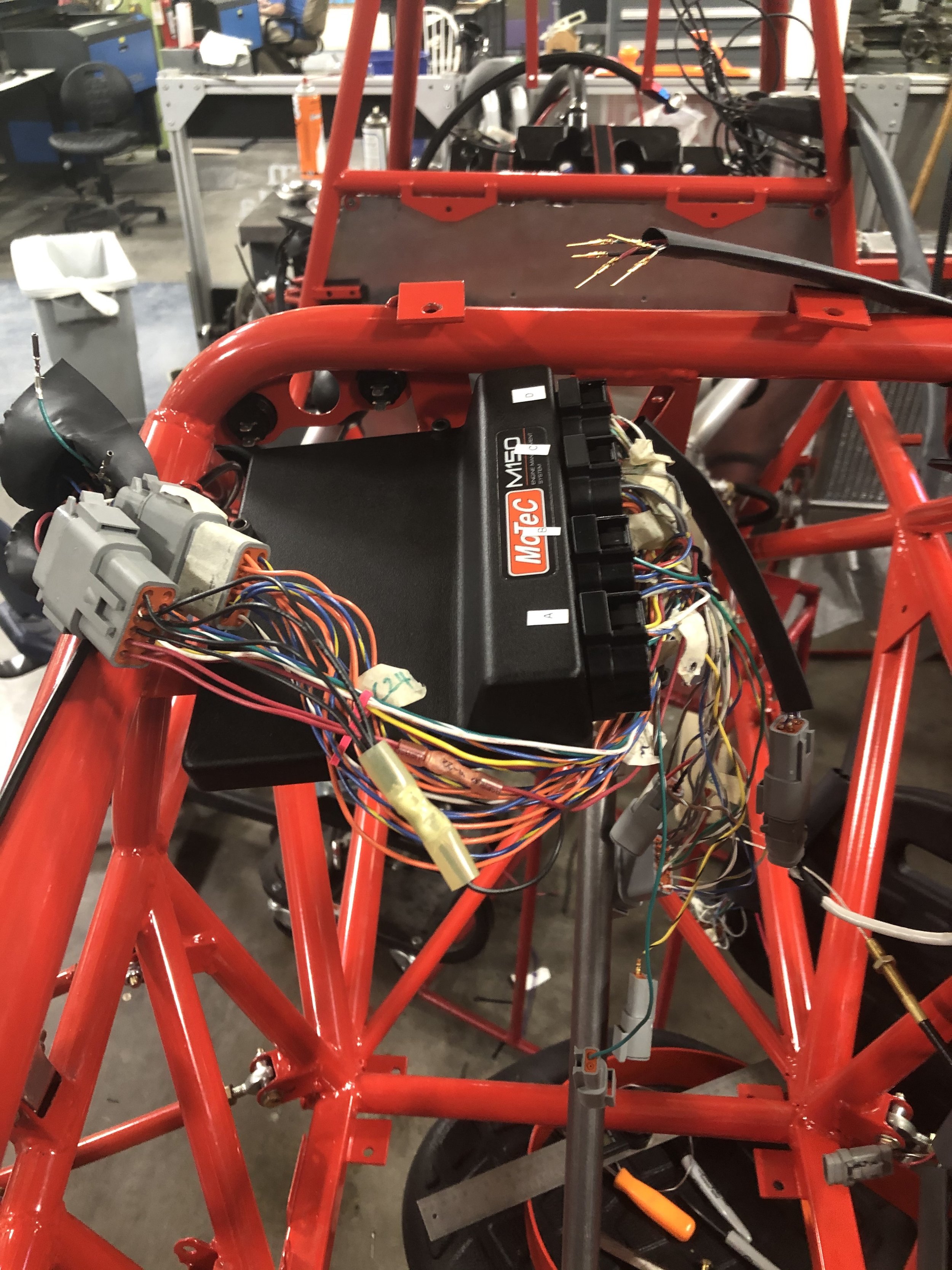
There are three control centers on the car: the ECU(big black box near the steering wheel), the dashboard MCU, and the relay system. The relay system primarily operates on 12V, while both the dashboard MCU and the ECU work on 5V.
We began by laying all of the wires which would connect the ECU to the various 5V sensors and actuators on the car. This alone took ~200 hours of work between 8 or so people. We then redesigned and laid wire for the relay system. This system supplies high current 12V power to the fuel pump, fan, starter motor, and several other 12V sensors on the car. It makes use of 4 independent relays, 3 kill switches and 3 differently fused power lines in order to meet the FSAE competition requirements. Beyond laying wire, we also needed to redesign the physical mounting of the relays. To do this, I designed, 3D printed, then painted the relay holder pictured below.
The final control center on the car is the dashboard MCU - more on that below!


Driver Controls Lead
I’m also the driver controls lead! This has meant building a lightweight, detatcheable steering wheel and designing and buildng the electronics and physical components for gear shifting, speed display, and oil pressure. Luckily, much of this work was done by the fantastic Scott Huson before my time(including having the aluminum skeleton jet cut and the 3D printed grips designed). My work on this included configuring communication via a CAN bus between the ECU and a Teensy 4.0 MCU, coding an LCD display, testing and assembling shifting paddles, electrically wiring custom elements for a quick connect terminal that was missing parts, and hooking up steering wheel buttons to the ECU.
Final Wheel, back side, grips, shifting paddles, starter button attached

“How are you going drive without a wheel? You ain’t.”
-Someone maybe

